
2020 is approaching, have these fuel cell technical indicators of the US Department of Energy (DOE) been completed?
release time:
2019-12-16
Cost, performance and durability are key challenges for the commercialization of fuel cells. For the key materials of PEM fuel cells (proton membrane, electrocatalyst, membrane electrode and bipolar plate), key components (stack, humidifier and air compressor) and fuel cell system, the US DOE has made recommendations for the above 8 items. Technology goals for 2020. 2020 is approaching, can you complete these fuel cell technical indicators of the US DOE?
Cost, performance and durability are key challenges for the commercialization of fuel cells. For the key materials of PEM fuel cells (proton membrane, electrocatalyst, membrane electrode and bipolar plate), key components (stack, humidifier and air compressor) and fuel cell system, the US DOE has made recommendations for the above 8 items. Technology goals for 2020. 2020 is approaching, can you complete these fuel cell technical indicators of the US DOE?
As a division of the US Department of Energy's Office of Energy Efficiency and Renewable Energy, the Fuel Cell Technology Division's "Multi-Year Research, Development and Demonstration Plan" specifies the goals, objectives and objectives of all activities related to fuel cells. , technical goals, tasks and timetables. Among them, for proton exchange membrane fuel cells for vehicles in the transportation field, the project document shows the technical goals of proton membranes, electrocatalysts, membrane electrodes, bipolar plates, stacks, humidifiers, air compressors and fuel systems by 2020.
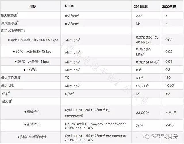
proton exchange membrane
Superscript annotation:
a Membrane electrodes were tested in oxygen or hydrogen at a temperature of 80°C, the gas was fully wetted, and the total pressure was 1 atm.
b Nanofiber-supported 14 μm PFIA membrane.
c Enhanced and chemically stabilized PFIA membrane.
d Cost of mass production (500,000 80 kW systems per year).
e Proton membrane cost to produce 500,000 systems per year.
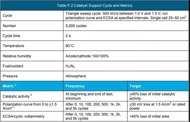
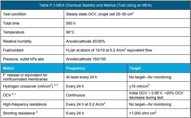
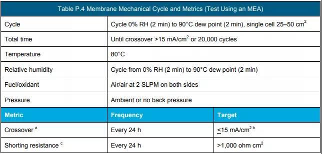
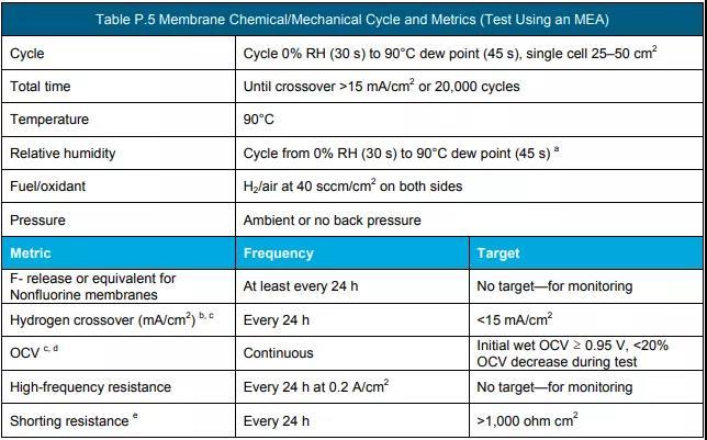
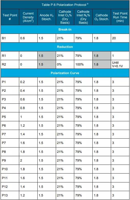
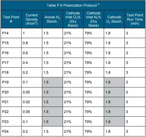
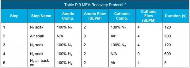
f Measure according to the protocol in Table P.3, Table P.4 and Table P.5. (See the end of the text for all schedules and figures)
g The permeation amount of 0.1 sccm/cm2 under the conditions of 50 kPa differential pressure, 80 °C and 100% RH can be used as an equivalent reference.
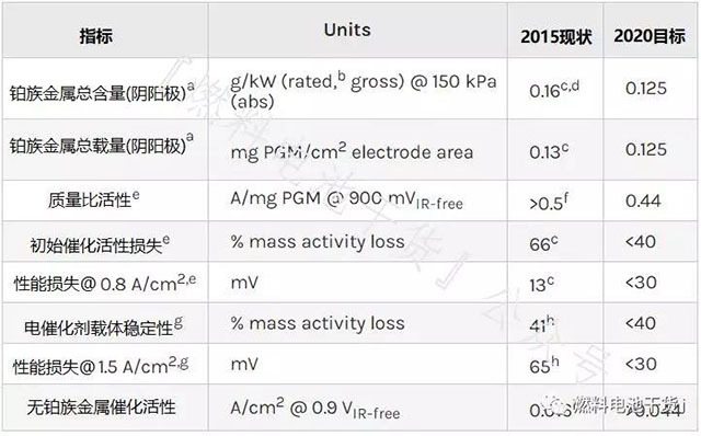
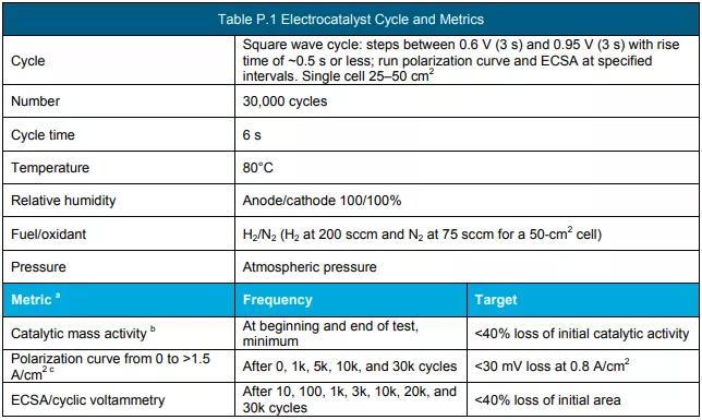
Electrocatalyst
Superscript annotation:
a Further reductions in precious metal content and loading may be possible to achieve system cost targets.
b The rated power operating point depends on the membrane electrode temperature. Based on the target value Q/ΔTi=1.45 kW/°C, the rated operating point voltage V=77.6/(22.1+T[°C]) is defined. The membrane electrode temperature is approximately equal to the stack coolant outlet temperature. For the definition of Q/ΔTi, see Note i of the stack specification.
c Refer to the 2014 Annual Value Assessment of "High Performance, Durability, and Low Cost Membrane Electrode Assemblies" published by Steinbach et al.
d Based on the total power of the membrane electrode at 150 kPa absolute pressure and measured at 0.692 V and 90°C, satisfying Q/ΔT<1.45 kW/°C. At an absolute pressure of 250 kPa, the target value is 0.12 g/kW.
e Measured using the protocol in Table P.1.
f Refer to the 2014 Annual Value Assessment of “Highly Active Desulfurization Catalysts” by Kongkanand et al., General Motors.
g Measure using the protocol in Table P.2.
h Refer to B. Popov et al. 2015 "Development of ultra-low-doped Pt cathode catalysts for PEM fuel cells" annual value assessment.
i Refer to the 2016 Annual Value Assessment of “Non-precious Metal Fuel Cell Cathodes: Catalyst Development and Electrode Structure Design” by P. Zelenay et al., LANL Institute.
j The target value corresponds to the target catalyst mass specific activity of 0.44 A/mgPGM at a loading of 0.1 mgPGM/cm2. (PGM: Platinum group metal)
Membrane electrode
Superscript annotation:
a Cost of mass production (500,000 80 kWnet systems per year).
b MEA cost for producing 50 systems per year.
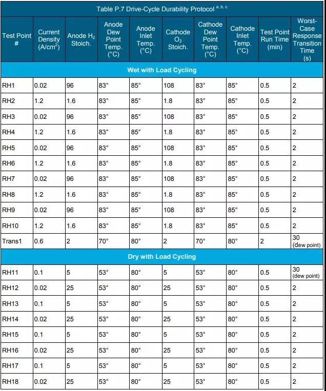
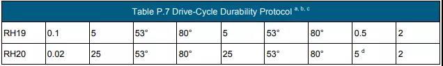
c According to the durability test procedure in Table P.7, the Gore membrane electrode using 510 catalyst (0.2/0.4 mgPGM/cm2 anode/cathode loading) before the voltage drop by 10% in the 1.0-1.5 A/cm2 electric density interval time.
d The temperature range is from 80°C to the maximum temperature or higher. <10% drop in power rating after testing according to polarization curves and durability testing protocols in Tables P.6 and P.7.
e Measured according to the protocol in Table P.8, the voltage drop is less than 5% at 1.2 A/cm2 electrical density operation.
f Measured using the polarization curve protocol in Table P.6.
g Refer to General Motors Corporation Kongkanand et al. 2014 Annual Progress Report on "Highly Active Desulfurization Catalysts".
h Measured using the polarization curve protocol in Table P.6, but can use any temperature up to the maximum operating temperature with a maximum inlet RH of 40%. Note b is the same for the rated power operating point and electrocatalyst technology target.
i The area specific power is 810 mW/cm2 when the absolute pressure is 150 kPa, and the area specific power is 1060 mW/cm2 when the absolute pressure is 250 kPa.
j Use the ratio of voltage at 30°C to voltage at 80°C for 1.0 A/cm2 electrical density operation based on the polarization curve measurements in Table P.6. Dew point 25°C for 30°C temperature operation only.
k Based on tests performed at LANL using Gore membrane electrodes with high cathode loading (0.1/0.4 mgPGM/cm2 positive/negative) and SGL GDL (25BC/25BC).
l Use the ratio of voltage at 90°C to voltage at 80°C under 1.0 A/cm2 electrical density operation based on the polarization curve protocol in Table P.6. Dew point 59°C for 90°C and 80°C temperature operation.
m Use the ratio of the voltage at transient 30°C to the voltage at steady-state operation at 1.0 A/cm2 at 80°C using the protocol based on the polarization curves in Table P.6. Dew point 25°C for 30°C temperature operation only. The 30°C transient condition refers to the current density of 1 A/cm2 for at least 15 minutes, then without changing the operating conditions, it is reduced to 0.1 A/cm2 and continued for 3 minutes; after 3 minutes, the current density is restored to 1 A/cm2 cm2, measure the voltage for 5 seconds after returning to 1 A/cm2.
bipolar plate

Superscript annotation:
a Cost of membrane electrodes to achieve 1000 mW/cm2 performance and mass production (500,000 80 kW systems per year).
b Cost of bipolar plates to produce 500,000 systems per year.
c Refer to Treadstone C.H. Wang's 2012 Annual Progress Report on "Low-cost Proton Exchange Membrane Fuel Cell Metal Bipolar Plates".
d According to standard gas transmission test (ASTM D1434).
e C.H. Wang (Treadstone), private communication, October 2014.
f Blunk, et al., J. Power Sources 159 (2006) 533–542.
g pH 3 0.1ppm HF, 80°C, peak active current<1e-6 A/cm2 (0.1 mV/s dynamic voltage test, -0.4 V to +0.6 V (Ag/AgCl)), purged with Ar.
h Kumar, M. Ricketts, and S. Hirano, "Ex-situ evaluation of nanometer range gold coating on stainless steel substrate for automotive polymer electrolyte membrane fuel cell bipolar plate," Journal of Power Sources 195 (2010): 1401–1407, September 2009.
i pH 3 0.1ppm HF, 80°C, passive current<5e-8 A/cm2 (+0.6V (Ag/AgCl) potentiostatic test over 24 h), aerated solution.
j See O. Adrinowycz et al., GrafTech's 2009 Annual Progress Report on "Next-Generation Bipolar Plates for Automotive PEM Fuel Cells".
k includes the interfacial contact resistance measured according to the method of Wang et al. Wang, et al. J. Power Sources 115 (2003) 243–251 at 200 psi (138 N/cm2).
I ASTM-D 790-10 Standard Test Method for Flexural Properties of Unreinforced and Reinforced Plastics and Electrical Insulating Materials.
m Refer to Porvair's D. Haack et al. 2007 Annual Progress Report on Carbon-Carbon Bipolar Plates.
n According to ASTM E8M-01 Standard Test Methods for Tensile Testing of Metallic Materials or other methods.
o Refer to Oak Ridge National Laboratory M. Brady et al. 2010 Annual Progress Report on Metal Nitride Bipolar Plates.
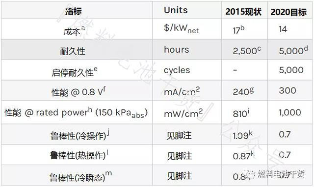
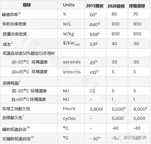
stack
Superscript annotation:
The stacks referred to in this section do not include fuel cell accessories such as hydrogen storage, electronics, drive and thermal, water, and air management systems.
c Net power (stack power minus BOP power). The volume is the "box" volume, including dead space.
d Press Release: Toyota Motor Corporation announced on September 24, 2012 the status of its future technology development.
e M. Hanlon, "Nissan doubles power density with new Fuel Cell Stack," Oct 13, 2011.
f Measured using the polarization curve protocol in Table P.6.
g Cost of mass production (500,000 stacks per year).
h Based on state-of-the-art component analysis at laboratory scale developed and validated under the DOE Fuel Cell Technology Office Fuel Cell sub-program, and producing 500,000 units per year.
i Same as Membrane Electrode Technology Target Note d.
j Refer to J. Kurtz et al. “Annual Fuel Cell Electric Vehicle Assessment” (2015 Annual Value Assessment) report, 10% voltage derating.
k The voltage drop at the 1.2 A/cm2 electrical density operating point is less than 5% measured according to the protocol in Table P.8.
l Q/ΔTi=[battery pack power (90 kW) x (1.25 V-voltage at rated power)/(voltage at rated power)]/[(battery pack coolant temperature-ambient temperature]]. Technical target assumptions 80 kW net power requires a 90 kW power stack and is measured using the polarization curve protocol in Table P.6 (except for inlet humidification and coolant outlet temperature). Inlet humidification up to RH40%, coolant outlet temperature up to maximum operating Temperature, cathode and anode inlet pressure up to 150 kPa (absolute value).
m Based on 0.67 V and stack coolant outlet temperature of 80°C.
n is the same as the membrane electrode annotation j.
o Same as Membrane Electrode Note I.
p is the same as the membrane electrode annotation m.
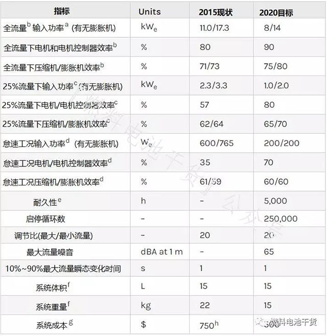
air compressor
Superscript annotation:
a The input power of the motor controller in the bench test of the fully integrated air compressor system. A fully integrated air compressor system includes control system electronics, filters, and other air equipment for cooling.
b Compressor: flow 92 g/s, discharge pressure 2.5 bar (absolute); inlet conditions 40°C, 25% RH. Expander: Flow 88 g/s, inlet pressure 2.2 bar (absolute), inlet conditions 70°C, 100% RH.
c Compressor: Flow 23 g/s, minimum discharge pressure 1.5 bar (absolute); inlet conditions 40°C, 25% RH. Expander: Flow 23 g/s, inlet pressure 1.4 bar (absolute), inlet conditions 70°C, 100% RH.
d Compressor: Flow 4.6 g/s, minimum discharge pressure 1.2 bar (absolute); inlet conditions 40°C, 25% RH. Expander: flow 4.6 g/s, < compressor discharge pressure, inlet conditions 70°C, 20% RH.
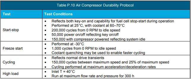
e Perform the durability test according to the protocol in Table P.10.
f Weight and volume include motor and motor controller.
g Annual production of 500,000 sets.
h Includes the cost of manufacturing compressors, expanders and motor controllers for 500,000 systems per year.
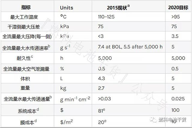
humidifier
Superscript annotation:
a Refer to the February 2013 Gore report "Materials and Modules for Low-Cost, High-Performance Fuel Cell Humidifiers".
b Incoming dry air: dry air flow 3000 SLPM, 183 kPa (absolute value), 80°C, 0%RH. Incoming moist air: dry air flow 2600 SLPM, 160 kPa (absolute value), 80°C, 85% RH.
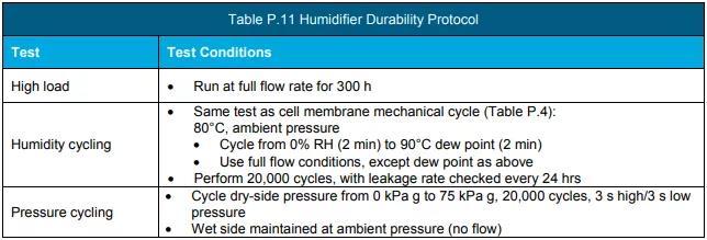
c Perform the durability test according to the protocol in Table P.11.
d Cost of mass production (500,000 80 kW systems per year).
e Refer to DOE 15015 Hydrogen and Fuel Cell Program Record "Fuel Cell System Costs - 2015".
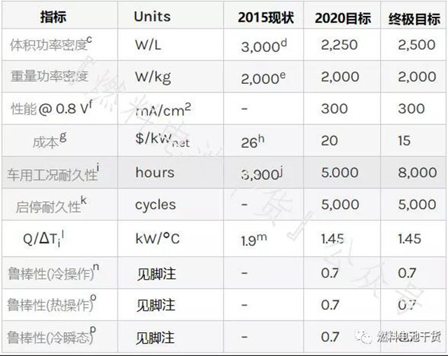
system
Superscript annotation:
a Technical targets exclude hydrogen storage, electronics and drives.
b Ratio of DC output energy to fuel hydrogen lower heating value. Peak efficiency is less than 25% of rated power.
c W. Sung, Y. Song, K. Yu, and T. Lim, "Recent Advances in the Development of Hyundai-Kia's Fuel Cell Electric Vehicles," SAE Int. J. Engines 3.1 (2010): 768–772, doi : 10.4271/2010-01-1089.
d J. Juriga, Hyundai Motor Group's Development of the Fuel Cell Electric Vehicle, May 10, 2012.
e U. Eberle, B. Muller, and R von Helmolt, Energy & Environmental Science 5 (2012): 8780.
f Cost of mass production (500,000 systems per year).
g is the same as the stack technology target annotation h.
h Based on averages reported at the 2010 SAE World Congress (W. Sung, Y-I. Song, KKH Yu, T.W. Lim, SAE-2-10-01-1089).
i Low calorific value energy of hydrogen, including electricity consumed during low temperature start-up.
j is the same as the stack technology target annotation j.
k is the same as stack technology target annotation i.
l Same as stack technical target annotation k.
m Soak for 8 hours at the specified temperature.
n Press release: Honda unveils FCX concept, September 25, 2006; Associated Press, Toyota develops new fuel cell hybrid, June 6, 2008.
Schedules and drawings:

Related news

No. 39, Qingshi Road, Jimo City, Qingdao, Shandong Province